





Tension Gas Springs: A Complete Selection Guide
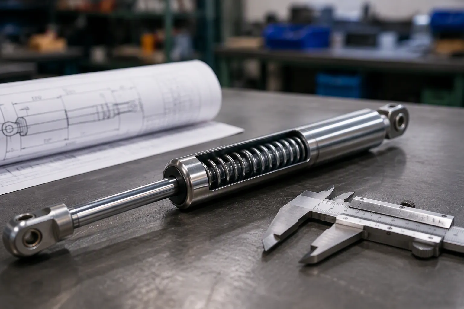
Picture this: a machinery safety guard crashes down without warning. The tension gas springs failed silently. Now the hatch won't stay open, creating a hazard for every operator nearby.
Choosing the right gas spring requires matching force, stroke, and mounting to your application's needs. This guide walks through key selection factors, a step-by-step process, and common mistakes. Manufacturers like JUTENG offer options from 5N to 3000N, accommodating diverse requirements.
Poor selection leads to safety risks and premature wear. The right gas spring delivers reliable performance for years. With practical knowledge, you can make a confident, informed decision for your specific application.
Key Takeaways
Tension gas springs pull components together, unlike compression springs that push outward.
Calculate required force by multiplying mass by gravity and adjusting for leverage.
Measure stroke length as the rod travel distance, not as the overall spring length.
Mount tension gas springs rod-down within 60 degrees of vertical for proper lubrication.
Always add a 10-15% safety margin to force calculations for reliable operation.
Choose Viton seals for extreme temperatures or corrosive environments to prevent failure.
Consult a manufacturer for 3D modeling and custom solutions to avoid costly errors.
Understanding Tension Gas Springs
What Are Tension Gas Springs?
Definition and Working Principle
A tension gas spring delivers a pulling force rather than a pushing one. Often referred to as traction gas springs in manufacturing catalogs like JUTENG's, these devices retract when at rest and extend under a pulling force. They store energy in compressed nitrogen gas inside a sealed steel cylinder.
The internal mechanism relies on precise engineering. A precision rod attaches to a piston inside the cylinder. The cylinder contains pressurized nitrogen gas and oil. When an external force pulls the rod outward, the piston moves, and the gas volume changes. According to Boyle's Law, pressure rises as gas volume decreases. The force equals the pressure differential acting on the rod's cross-sectional area. The oil provides damping, slowing movement and preventing sudden, jarring motion. This design ensures smooth, controlled operation throughout the entire stroke.
Tension vs. Compression: Key Differences
Understanding the distinction between these two types of gas springs prevents costly selection errors. The table below summarizes the fundamental difference:
Spring Type | Force Direction |
|---|---|
Tension Gas Spring | Pulling force (inward) |
Compression Gas Spring | Pushing force (outward) |
Compression gas springs extend to push objects apart or lift lids upward. Tension gas springs pull components together or hold them in a closed position. This directional difference changes every aspect of mounting, force calculation, and application design. Selecting the wrong type means the spring works against your mechanism rather than with it.
Common Applications for Tension Gas Springs
Industrial Machinery and Safety Guards
Industrial settings demand reliable motion control. Tension gas springs excel in applications involving hatches, heavy lids, and adjustable equipment where manual or automatic locking ensures secure positioning. OEM manufacturers and industrial equipment builders rely on these components for specialized engineering needs. A safety guard that must stay closed during operation benefits from the consistent pulling force these springs provide.
Automotive, Marine, and Aerospace Uses
Transportation industries require components that withstand vibration and environmental stress. Tension gas springs hold access panels closed, secure storage compartments, and assist with hatch operations. Marine environments demand corrosion resistance, while aerospace applications require precise force characteristics. JUTENG offers forces ranging from 5N to 3000N, accommodating these diverse requirements.
Furniture and Medical Equipment
The benefits of tension gas springs extend to everyday products. Adjustable furniture mechanisms use these springs to control movement and maintain position. Medical beds incorporate lockable gas springs, another type within JUTENG's product line, allowing caregivers to secure positions safely. Dampers control motion speed in equipment requiring gentle handling. These applications demonstrate how understanding the function—lifting, counterbalancing, or damping—guides proper selection.
Each application demands a controlled pulling force to draw a component into position. This functional requirement defines tension gas springs and separates them from compression alternatives. Recognizing the application's core function before evaluating specifications simplifies the entire selection process. Gas spring operation depends on matching the spring's behavior to the mechanism's needs, not the reverse.
Key Selection Factors for Gas Springs
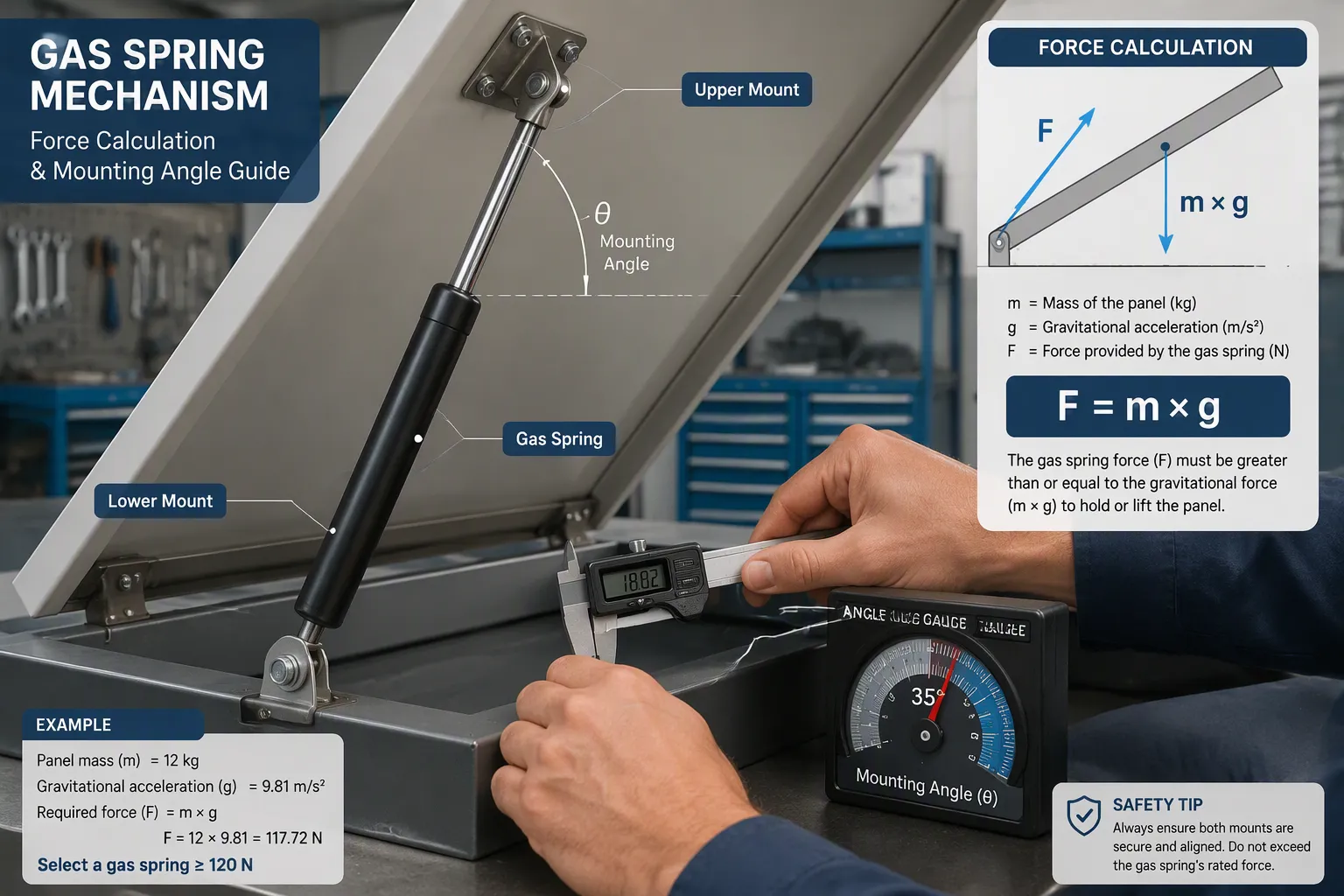
Force, stroke, and mounting angle interact to determine whether a gas spring performs as intended. Overlooking any one factor leads to early failure or dangerous operation. The following sections address each element in detail, providing a clear path to correct specification.
Force Requirements: Calculating the Pull
Understanding Force Units (Newtons, Pounds)
Force is the most critical selection factor. Manufacturers specify gas springs in Newtons (N) or pound-force (lbf). One Newton equals the force required to accelerate one kilogram at one meter per second squared. One pound-force converts to roughly 4.45 Newtons. JUTENG offers forces from 5N to 3000N, covering light furniture lids to heavy industrial safety guards. Understanding these units allows direct comparison between your calculated requirement and the available product range.
Formula for Force Calculation (F = m × g)
The basic starting point uses Newton’s second law. Multiply the supported mass in kilograms by gravitational acceleration, 9.81 m/s². This gives the static weight in Newtons. However, this number alone is insufficient because the geometry of the mechanism alters the effective force demand.
The moment balance equation expresses this fully: required gas spring force equals (weight × distance to center of gravity × cosine of opening angle) divided by (leverage distance × sine of mounting angle). Every variable influences the final value.
The useful lifting effect depends on the distance between the gas spring's force line and the hinge, known as the moment arm. As the panel rotates, mounting points move, changing the moment arm and thus the lifting torque even if the spring force is constant. Near the closed position, geometry gives the gas spring little leverage, requiring a higher force. Mid-stroke leverage improves, making support easier.
Adjusting for Leverage and Mounting Angle
The relationship between load and support factors determines the correct specification. The table below compares the two sides of the equation.
Load Side (creates closing torque) | Support Side (provides lifting torque) |
|---|---|
Panel or lid weight | Gas spring force |
Distance from hinge to center of gravity | Mounting point position |
Opening angle during movement | Gas spring installation angle |
Motion path through opening range |
The reality is that a heavier lid does not always need a stronger gas spring. A longer lever arm can reduce the required force substantially. Conversely, a poor mounting angle multiplies the force demand. For every application, calculate the force across the full motion range. A 10–15% safety margin compensates for manufacturing tolerances and seal friction.
Stroke Length: Matching Travel Distance
Measuring Stroke Correctly
Stroke length determines how far the connected component moves. A mismatch prevents the lid from opening completely or forces the spring into mechanical interference. Use a consistent procedure for measurement.
Fully compress the tension gas spring so the rod is pushed completely into the body.
Measure the exposed rod length while it is in this fully compressed state.
Fully extend the rod to its maximum open position.
Subtract the compressed length from the extended length. The difference is the stroke.
Extended vs. Compressed Length Considerations
Extended length and compressed length define the physical boundaries of the installation. The table below clarifies each term.
Term | Definition |
|---|---|
Extended Length | Measured center to center between mounting points when the gas spring is fully open. |
Compressed Length | Measured when the gas spring is fully closed. |
Stroke Length | The difference between extended and compressed length. |
The compressed length must fit within the available cavity when the mechanism is closed. The extended length determines the total reach when the mechanism opens. JUTENG offers standard and long construction types for traction gas springs, accommodating varied space constraints.
Mounting Options and Configurations
Clevis, Rod End, and Bracket Types
Mounting hardware connects the gas spring to the mechanism. Clevis mounts allow rotation around one axis. Rod ends provide threaded attachment points for precise alignment. Brackets offer a fixed connection angle. The correct mount ensures the spring’s force line stays aligned with the designed geometry. JUTENG engineers can recommend the appropriate style based on your application’s pivot points and attachment surfaces.
Impact of Mounting Position on Performance
Mounting position directly affects service life. Standard gas springs must be mounted rod-down within 60° of vertical. This orientation keeps oil in contact with the rod seal, ensuring proper lubrication and damping. Consider the following points for reliable operation.
Rod-down orientation within 60° of vertical maintains seal lubrication.
Rod-up or near-horizontal mounting dries the seal and reduces life.
For non-ideal orientations, specify an oil chamber or fully damped gas spring.
Environmental conditions also matter. Temperature swings, humidity, and UV exposure degrade seals and oil over time. JUTENG uses flame-retardant oil and hermetic sealing to ensure durability across all common environments. These considerations guarantee that the gas spring delivers consistent performance for its full rated life.
Step-by-Step Selection Process
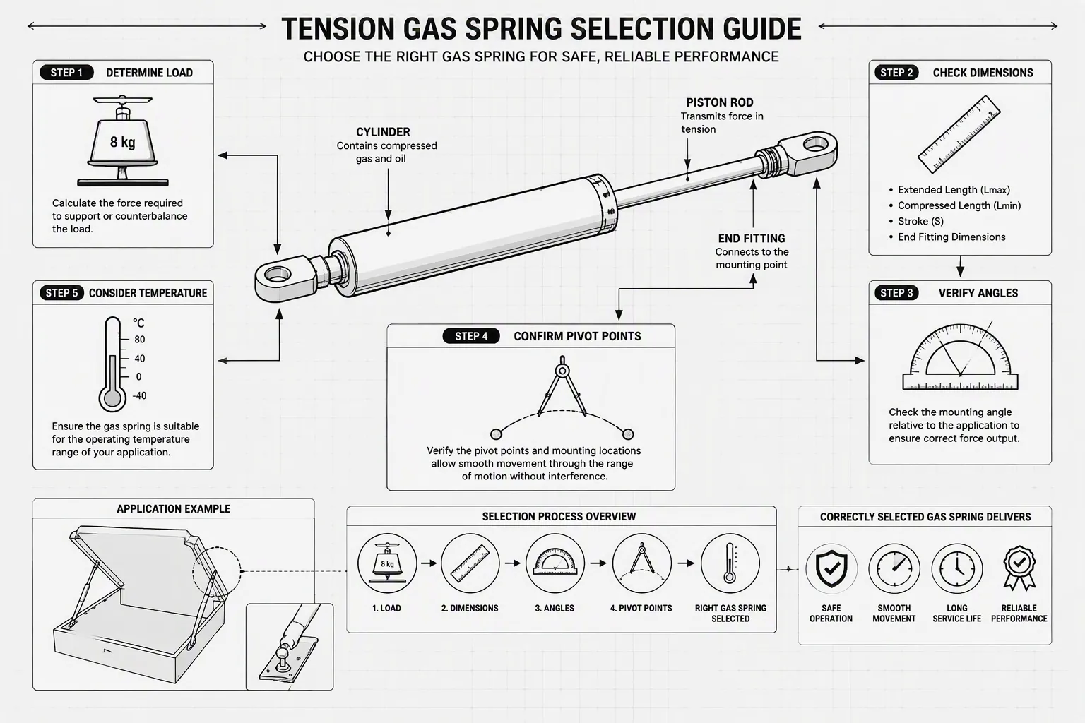
Selecting the correct tension gas spring follows a logical sequence. Each step builds on the previous one. Skipping ahead or guessing at values leads to the exact failures described earlier. Work through the process methodically, and the right specification becomes clear.
Step 1: Define Your Application Requirements
Identify the Function (Lift, Counterbalance, Dampen)
Every mechanism serves one primary purpose. A safety guard needs to stay closed under vibration. A storage hatch must remain open during loading. An access panel requires controlled motion to prevent slamming. Name the function first. This decision determines whether you need a tension spring, a compression spring, or a damper. For a tension gas spring, the function is always to pull a component into a secure position or hold it there against an opposing force.
Gather Weight, Dimensions, and Motion Data
Accurate selection depends on accurate inputs. Collect the following data before contacting any manufacturer:
Mass of the moving component in kilograms
Location of the center of gravity relative to the hinge
Hinge or pivot position and its orientation
Required opening angle for the application
Stroke, extended length, and compressed length available in the mounting space
Retracted-force direction, which matters specifically for tension gas springs
Available installation length for the spring body and rod
Mounting points and end fittings, ensuring pivot alignment without side loading
Operating environment, including temperature, humidity, corrosion, and contamination levels
This list covers every variable that influences the final specification. A machinery safety guard weighing 8 kilograms, for example, requires knowing where its center of gravity sits. If the guard pivots from a hinge at one edge, the distance from that hinge to the center of gravity becomes a critical measurement. The opening angle determines how far the spring must travel and how the leverage changes through the motion.
Step 2: Calculate the Required Force
Use the Formula: Force = Mass × Gravity
The starting point converts mass into weight. Multiply the mass in kilograms by 9.81, the standard gravitational acceleration in meters per second squared. An 8 kg lid produces a weight of 78.48 Newtons. This value alone does not tell you the spring force. The geometry of the mechanism transforms that weight into a torque around the hinge.
The core formula for calculating the minimum required force (F) of a gas spring is F = (W × D) / L, where:
W is the object's weight in Newtons, calculated as mass (kg) × 9.81 (standard gravity).
D is the distance from the hinge to the center of gravity (in meters).
L is the distance from the hinge to the gas spring attachment point (in meters).
Worked example: For an 8 kg lid (W = 78.48 N), with D = 0.4 m and L = 0.6 m, the required force is F = (78.48 × 0.4) / 0.6 = 52.32 N.
This calculation assumes the spring mounts perpendicular to the lid at full extension. Real installations rarely achieve this ideal geometry. The mounting angle changes as the lid opens, altering the effective leverage throughout the stroke.
Factor in Leverage and Safety Margin (10-15%)
The formula above gives a theoretical minimum. Real-world conditions demand more. Industry guidance varies, but a common recommendation applies a 10% to 15% safety factor to the calculated force for heavy-duty installations. This margin accounts for ambient wind resistance, structural friction, and temperature fluctuations that affect gas spring performance.
Some engineering suppliers suggest a more conservative approach. A safety factor of 1.2 to 1.5 times the calculated force corresponds to a 20% to 50% margin over the theoretical minimum. This larger buffer compensates for manufacturing tolerances, component wear, and the natural 3-5% annual force loss due to gas permeation.
For the worked example, applying a 15% safety margin raises the specification from 52.32 N to approximately 60 N. A manufacturer offering forces in standard increments would likely recommend a 60 N or 65 N spring. The extra force ensures the guard stays closed securely without requiring excessive effort to open.
Step 3: Verify Spatial Constraints and Interference
Validating the Physical Envelope
Once the required stroke is calculated, the critical next step is verifying the physical envelope within your mechanism. Ensure the compressed length does not bottom out against the cylinder base during operation, and the extended length clears all adjacent mechanical linkages. A common error involves ordering a spring with the correct force but dimensions that cause physical interference at the extremes of travel.
Leveraging OEM/ODM Customization
If standard stroke lengths or body diameters cause interference in your compact design, off-the-shelf components will not suffice. This is where JUTENG’s OEM/ODM capabilities become vital. With an annual production capacity of 1.5 million units, JUTENG's engineering team can customize the cylinder body, rod diameter, or thread types to fit your exact spatial envelope. By utilizing CAD systems such as CATIA and SolidWorks, JUTENG can simulate the tension gas spring's motion path within your specific assembly, identifying leverage dead-zones or collision risks before a single unit is manufactured.
Common Mistakes to Avoid
Even experienced engineers make errors when selecting tension gas springs. These mistakes lead to premature failure, safety hazards, and unnecessary replacement costs. Understanding the most frequent pitfalls helps you avoid them.
Overlooking Dynamic Force Changes
Ignoring Leverage Ratios at Different Angles
Many buyers calculate force at a single position. They assume that value works throughout the full motion. This assumption fails because leverage changes with angle.
Due to hinge leverage and mounting angles, only 30-60% of a gas spring's rated force converts to usable lifting force. The actual usable force varies significantly with mounting geometry. Consider an application with two different mounting configurations:
Angle (deg) | Vertical force component (% of axial force) | Required spring force (per spring, lbf) |
|---|---|---|
32 (closed) | 53% (sin 32) | 56.5 |
54 (open) | 81% (sin 54) | 37 |
Configuration A shows a moderate force variation from 56.5 lbf to 37 lbf. Configuration B with a 9° closed and 40° open angle requires 192 lbf when closed and only 46.8 lbf when open. The force spike at the closed position results from poor leverage. Ignoring this variation causes undersized springs that cannot hold the lid closed.
Misjudging Force Needs During Motion
Static calculations alone do not capture real-world conditions. Dynamic loads from moving masses generate forces 50-100% higher than static values due to acceleration and deceleration. An 8 kg lid swinging open creates a much higher demand than the same lid sitting still.
For dynamic applications, a safety factor of 1.5-2.0 is commonly applied during sizing. Industry standards escalate this to 2.0-2.5 when dynamic loads include acceleration and shock factors. These higher safety margins ensure reliable performance under varying force conditions during motion. Selecting by appearance or copying a force value from another application leads to incorrect counterbalancing and premature wear.
Incorrect Stroke Measurement
Confusing Stroke with Overall Length
Stroke and overall length are not the same. This confusion causes one of the most common ordering errors.
When used in the context of gas springs, stroke is the maximum distance the rod can travel.
The overall length (extended length) equals the sum of the closed length and the stroke. A spring with the correct force but a stroke too short for the application cannot open the lid fully. The spring bottoms out internally, causing damage and early leakage.
Failing to Account for Mounting Hardware
Allowing the gas spring to act as the mechanical stop leads to internal damage and early leakage. The mounting hardware takes up space and changes the effective compressed and extended lengths. Measure the full travel distance between mounting points with all hardware installed. Verify that the spring fits at both ends of travel without bottoming out, over-extending, or colliding with adjacent structure. Ignoring the hinge moment causes miscalculated force requirements and bent brackets.
Neglecting Environmental Factors
Using Standard Seals in Extreme Temperatures
Standard NBR seals work well in normal conditions. They fail quickly in high-temperature zones or around harsh chemicals.
For gas springs operating in these demanding environments, standard NBR seals are insufficient. The manufacturer recommends requesting custom gas springs built with Viton (FKM) seals, which offer far superior thermal and chemical resistance. PTFE and modified PTFE materials handle temperatures from −46°C to 180°C. PEEK washers maintain structural integrity across a 20°C–180°C range. Choosing the wrong seal material guarantees early failure.
Ignoring Corrosion Risks in Outdoor Settings
Installing the rod where it can be contaminated accelerates seal wear and causes premature failure. Outdoor applications expose the rod to moisture, salt, and debris. These contaminants score the rod surface and destroy the seal. Rod-down mounting within 60° of vertical keeps oil in contact with the rod seal. This orientation maintains proper lubrication and extends service life. For outdoor installations, specify corrosion-resistant materials and protective coatings like those offered in JUTENG's stainless steel series, ensuring durability in the harshest environments.
Selecting a tension gas spring follows a clear sequence. First identify the function of your mechanism. Calculate the required force using weight and leverage. Verify spatial constraints to avoid interference. Choose appropriate mounting hardware and consider environmental factors like temperature and corrosion. This systematic process removes guesswork and ensures reliable, long-lasting performance.
Need Help Sizing Your Tension Gas Spring?
Don't risk mechanical failure or safety hazards due to incorrect sizing. Send your CAD drawings, application parameters, or 3D models to JUTENG's engineering team for a free force calculation, spatial simulation, and custom quote.
Direct Email:gasspring@czjuteng.com
WhatsApp / WeChat:+86-18616235963 (Ms. Judy Lee)
Annual Capacity: 1.5 Million Units | OEM & ODM Supported
FAQ
How do I know if I need a tension gas spring or a compression gas spring?
Determine the direction of force your mechanism requires. Tension gas springs pull components together or hold them closed. Compression gas springs push outward to lift or open. Examine your application's motion path. If the lid or guard must stay secured against an opposing force, tension is correct.
What happens if I choose a gas spring with too much force?
Excessive force makes the mechanism difficult to open and creates unnecessary stress on hinges and mounting brackets. Operators may struggle to release safety guards. The spring can also overpower the structure, causing bending or premature wear. Always calculate force carefully and apply only a 10-15% safety margin.
Can I mount a tension gas spring in any orientation?
Orientation matters for service life. Standard gas springs should mount rod-down within 60° of vertical. This position keeps oil in contact with the rod seal for proper lubrication. Horizontal or rod-up mounting dries the seal and reduces lifespan. For unusual orientations, consult the manufacturer about special oil chamber designs.
How do temperature extremes affect gas spring performance?
Temperature changes alter internal gas pressure. Cold environments reduce force output, while heat increases it. Standard NBR seals degrade above 80°C or in chemical environments. For demanding conditions, request Viton (FKM) seals or PTFE components. These materials maintain performance from -46°C to 180°C.
What is the difference between stroke length and extended length?
Stroke length measures only the distance the rod travels from fully compressed to fully extended. Extended length describes the total physical size of the spring at full extension, including body and rod. Confusing these values leads to ordering springs that cannot open the mechanism completely.
How long does a quality tension gas spring last?
A well-manufactured spring delivers 10,000 to 50,000 double strokes without maintenance. JUTENG constructs springs with hermetic sealing to prevent gas leakage. Annual force loss of 3-5% occurs naturally due to gas permeation. Proper mounting and environmental protection maximize the operational lifespan.
Do I need to account for the weight of the mounting hardware?
Yes. Mounting brackets and clevis fittings occupy space and alter the effective compressed and extended lengths. Measure the full travel distance between mounting points with all hardware installed. Verify the spring fits at both extremes without bottoming out or over-extending. This prevents internal damage and early leakage.
What are the benefits of consulting a manufacturer before purchasing?
Manufacturer expertise prevents costly selection errors. JUTENG provides 3D modeling, component calculation, and simulation using CAD systems like CATIA and SolidWorks. Their engineering team reviews your application geometry and environmental conditions. This support ensures the correct specification for both standard and custom requirements.
Recent News
1.Traction vs. Compression Struts: Industrial Use
2026-07-152.Top Traction Gas Spring Manufacturers and Suppliers in 2026
2026-04-103.How traction gas springs function in modern applications
2026-06-084.Traction gas spring application
2025-08-165.Which is better, traction gas strut or compression strut?
2025-12-12