



Traction vs. Compression Gas Springs
The Difference Between Traction Gas Springs and Compression Gas Springs
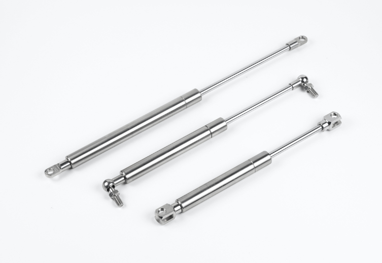
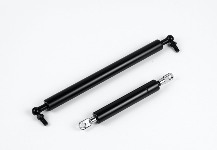
Engineers select specialized motion elements to manage heavy loads smoothly. Standard compression gas springs supply a continuous pushing force by extending outward. Conversely, a specialized traction gas spring generates a pulling force by retracting inward into the cylinder.
Selecting an improper direction compromises mechanical safety, equipment operation, and user ergonomics. Industry demand for these reliable components continues growing across global markets:
Metric | Value |
|---|---|
Global Industrial Gas Spring Market Size (2024) | 2,068.3 USD Million |
Projected Annual Growth Rate (CAGR, 2026-2035) | 4.0% |
Juteng leads this sector by offering over 300 customizable hydropneumatic solutions. Modern springs elevate automotive, medical, industrial, and furniture applications through precise force control.
Key Takeaways
Compression gas springs push outward to lift heavy doors, while traction gas springs pull inward to keep covers shut.
Engineers use compression springs in vehicle hoods and traction springs in medical equipment and belt drive systems.
Compression springs last longer because traction springs experience more seal friction during daily use.
Mounting springs vertically provides the strongest lifting/pulling power and prevents unnecessary wear on internal seals.
Juteng provides custom gas spring design services with precise force levels to keep modern industrial machines operating safely.
Overview of Compression Gas Springs
Push Mechanism and Stored Energy
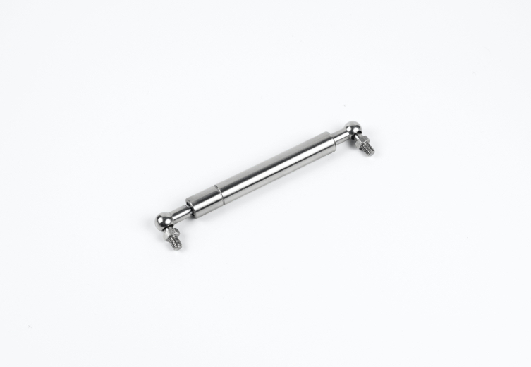
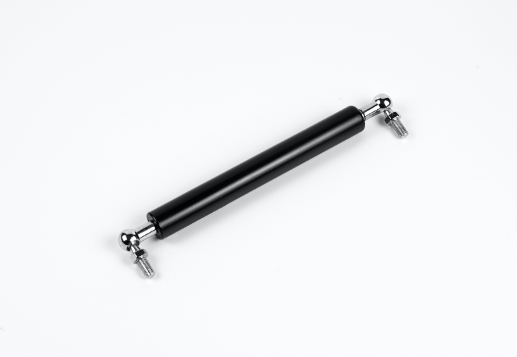
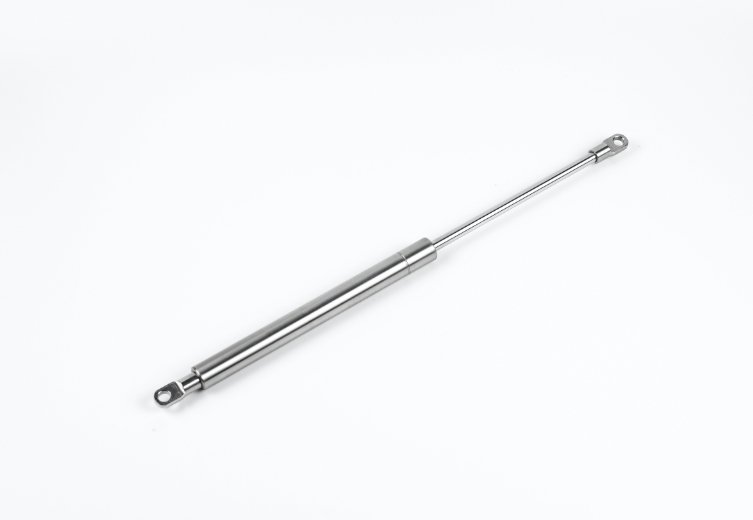
Compression gas springs maintain an extended default position during normal resting states. Non-flammable compressed nitrogen gas fills the internal cylinder chamber completely. This pressurized internal atmosphere drives the piston rod outward to produce a consistent pushing force. Juteng manufactures these versatile components using durable materials, including high-grade carbon steel and corrosion-resistant 304 stainless steel. Internal fluid lubricants protect internal dynamic seals and reduce operational friction.
Gas-charged elements provide superior energy storage capabilities compared to standard mechanical designs.
When compared to mechanical springs, gas springs are able to store, and exert, more energy.
This elevated force density allows engineers to achieve compact mechanical layouts without sacrificing lifting power. Piston movement compresses internal nitrogen gas further during manual closure, storing potential energy for subsequent opening cycles.
Common Lifting Applications
Industrial equipment manufacturers integrate these motion control components across diverse operating systems. Standard units deliver controlled force outputs ranging from 5N to 3000N. Primary lifting applications include automotive vehicle hoods, heavy industrial access hatches, and commercial cabinet doors. Every heavy-duty gas spring application demands precise weight balancing to ensure safe equipment operation. Integrated hydraulic damping cushions terminal movement near full stroke extension to safeguard expensive machinery components against heavy impact damage.
Understanding Traction Gas Springs
Mechanism of Traction Gas Springs
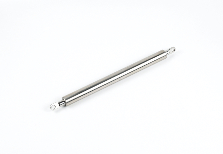
A standard traction gas spring operates in reverse compared to a compression element. Pressurized internal nitrogen gas acts on the piston inside the cylinder chamber. This design generates a continuous pulling force, pulling the piston rod back into the cylinder housing. Mechanical system designers utilize traction gas springs to hold doors, access hatches, or protective covers completely shut during system idle states.
Unlike traditional springs, traction gas springs maintain predictable force profiles throughout their operational stroke length. Specialized sealing systems contain internal gas pressure efficiently. Consequently, robust motion springs maintain accurate force levels inside demanding operating environments without requiring continuous manual adjustment.
Applications for Traction Gas Springs
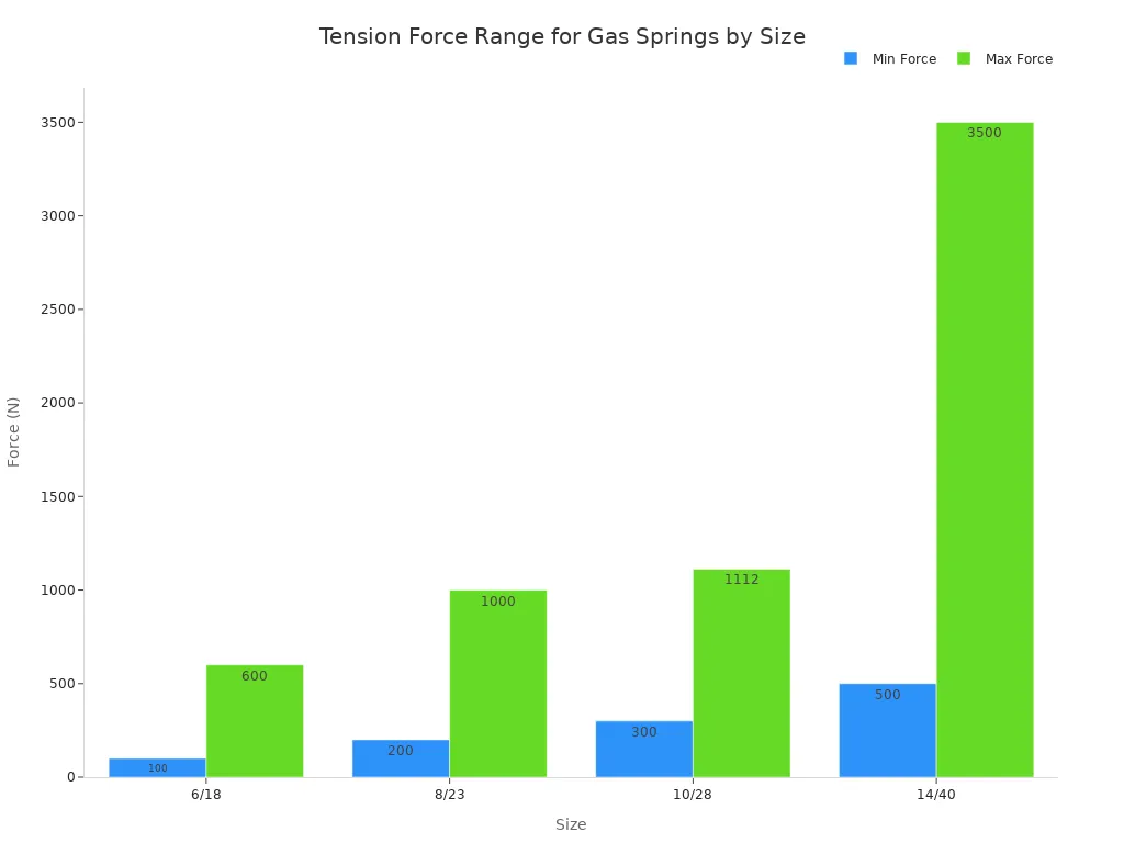
Engineers integrate traction gas springs into complex machinery setups across multiple commercial sectors. Every belt drive application requires reliable tension control to prevent power loss. Traction gas springs maintain optimal belt tightness continuously in high-vibration systems. The table below displays tension force ranges across standard cylinder sizes:
Size | Force Range (N) | Source |
|---|---|---|
6/18 | 100 - 600 | Industrial Catalog |
8/23 | 200 - 1,000 | Industrial Catalog |
10/28 | 300 - 1,112 | Industrial Catalog |
14/40 | 500 - 3,500 | Industrial Catalog |
Medical equipment manufacturers rely on traction gas springs for safe, quiet motion control. Within healthcare settings, a specialized traction gas spring (like the 10/22 series) provides controlled retraction to elevate patient safety and comfort. Primary healthcare applications include retractable scanner arms for medical imaging devices, adjustable hospital beds, and specialized physical therapy devices.
Key Functional and Mechanical Differences
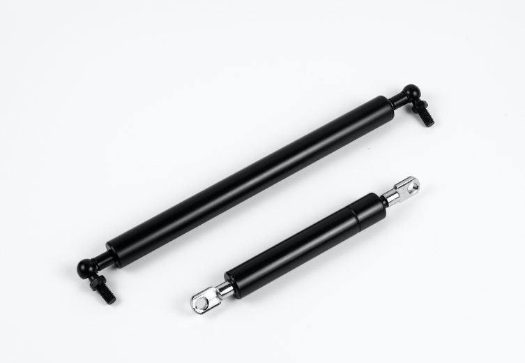
Direction of Force and Resting State
Mechanical system performance relies on structural motion orientation and static resting positions. Standard compression gas springs maintain an uncompressed, fully extended resting state. The piston rod remains extended outside the main cylinder housing until external physical loads force entry. Conversely, traction gas springs remain completely retracted inside the main cylinder during unactuated resting states.
Engineers choose specific mechanical configurations based on precise dimensional parameters. The following standard engineering specifications detail common structural dimensions and load characteristics at Juteng:
Juteng Series | Tube Diameter (mm) | Rod Diameter (mm) | Force Range (N) |
|---|---|---|---|
10/22 (Standard) | 22 | 10 | 120 - 700 |
12/25 | 25 | 12 | 500 - 2000 |
14/28 | 28 | 14 | 500 - 3500 |
Mechanical movement causes dynamic internal energy shifts during normal stroke execution. Internal seal friction creates distinct physical behaviors during active motion cycles.
Force Curve Analysis (Friction Effect):
Dynamic measurement reveals a consistent, quantifiable force difference.
Due to seal and piston friction, the force during compression (pushing) is measurably higher.
The force during extension (pulling) is correspondingly lower.
Designers must calculate dynamic operational forces accurately when integrating traction gas springs into mechanical assemblies.
Quantitative Force Relationship for Traction Springs:
The forces at the two ends of a gas traction spring (F1 and F2) are close in value.
The engineering specification gives a precise ratio: F1 : F2 ≈ 1 : 1.2.
Speed Control and Integrated Damping
Controlled linear motion requires specialized internal hydraulic design elements to manage physical travel speed. Modern springs utilize hydraulic fluid reservoirs to create smooth motion transition zones near terminal stroke boundaries. Internal fluid resistance provides terminal dampening to prevent dangerous end-position structural impacts.
Traction gas springs utilize inverted fluid chamber designs to supply steady resistance during internal retraction cycles. Hydraulic dampening absorbs excessive kinetic momentum as the piston rod returns into the housing.
Durability and Service Life Comparison
Lifespan Expectations and Seal Wear
Mechanical realities alter the operational lifespan between spring designs. A traction gas spring typically exhibits about half the service life of standard compression gas springs. Inverted pressure dynamics and continuous seal friction accelerate internal seal wear in traction designs. Juteng mitigates these mechanical challenges through rigorous manufacturing protocols and quality certifications. Standard testing procedures validate operational resilience across 10,000 to 50,000 double strokes.
Field performance analysis identifies several core operational factors that cause early unit failure:
Primary Cause | Failure Mechanism | Supporting Evidence / Example |
|---|---|---|
Seal Degradation & Contamination | Normal aging of HNBR seals combined with exposure to dust, grit, or washdown fluids on the extended rod. | A customer on a food-processing line experienced failures due to washdown residue, resolved by reviewing seal specification. |
Side-Loading | Lateral load caused by misaligned mounting points, leading to uneven seal wear. | Misalignment forces the rod to take unintended lateral loads, destroying the seal prematurely. |
Maintenance and Environmental Resilience
Hydropneumatic units operate as sealed systems. Routine maintenance requires no fluid additions or internal adjustments during regular service. Industrial-grade components achieve a normal lifetime ranging from 50,000 to 100,000 cycles under standard conditions. When a gas strut loses force and no longer holds loads safely, operators must replace the complete unit immediately. Juteng provides fully tested motion elements, delivering consistent operational performance across every industrial application.
Selection Guide for Engineering Projects
Force Calculation and Mounting Geometry
Engineers establish a clear decision framework based on required stroke length, force output requirements, and spatial mounting orientation. Calculating the baseline force output for springs in a lid application relies on fundamental torque balance:
F = (W × D) / L
In this equation, W represents total lid weight, D is the distance from the hinge to the center of gravity, and L is the distance from the hinge to the spring mounting point. Designers add 10-20% to account for real-world friction.
Custom Stroke and End Fitting Options
Selecting appropriate hardware accessories ensures smooth mechanical integration. Juteng provides complete technical support capabilities, offering precise CAD modeling, dynamic motion simulation for customized springs, and end fitting selection. Designers customize internal stroke lengths to fit tight spatial mounting layouts.
Standard compression components deliver a reliable pushing force to lift heavy structural access covers smoothly. Conversely, a traction gas spring produces a continuous pulling force to retract industrial components securely into safe resting positions.
Ready to optimize your mechanical design?
Contact Juteng's Engineering Team for a free CAD model, custom force calculations, and a competitive quote today!
FAQ
What is the main difference between a compression gas spring and a traction gas spring?
Compression gas springs generate outward pushing force to extend the piston rod. Traction gas springs operate in reverse, producing continuous pulling force to draw the piston rod into the cylinder.
Why do traction gas springs have a shorter service life than compression springs?
Inverted pressure dynamics create higher continuous friction against internal seals in traction springs. This additional seal wear typically reduces total service life to approximately half the operational lifespan of standard compression gas springs under similar working conditions.
What force output range do Juteng gas springs provide?
Juteng manufactures gas springs delivering consistent force outputs from 10N to 3500N. Technical support teams adjust internal nitrogen pressure during production to match exact customer requirements.
What structural materials ensure durability in Juteng gas springs?
Juteng constructs robust cylinder housings and piston rods using high-grade carbon steel and corrosion-resistant 304 stainless steel. Advanced internal fluid lubricants shield dynamic seal surfaces from premature wear, ensuring reliable performance across 50,000+ double strokes.