




The Ultimate Guide to Picking the Right Gas Spring for Your Auto
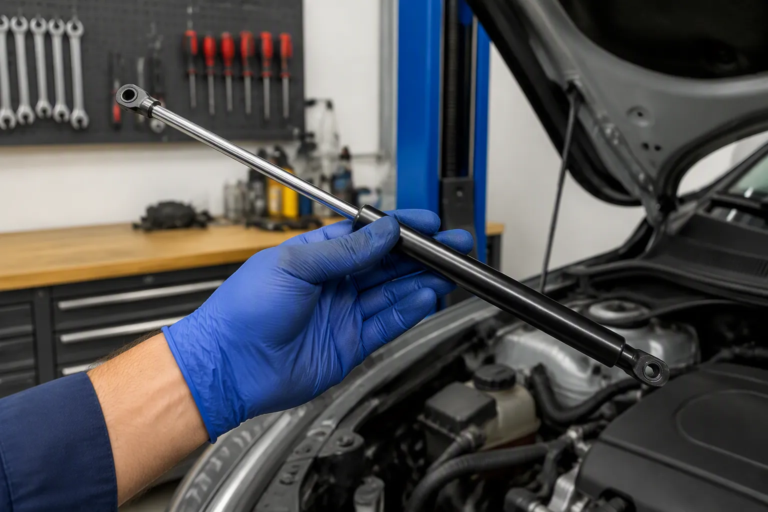
Selecting the right automotive gas spring for OEM vehicle design or aftermarket replacement requires precise engineering data rather than guesswork. Lid weight and center of gravity determine the exact force needed to lift a hood or trunk safely. An incorrect force calculation causes the lid to slam shut violently or fail to stay open. Stroke length defines the travel distance, while mounting points dictate the physical fit and alignment within the vehicle's body structure. Each measurement directly impacts the final performance and NVH (Noise, Vibration, and Harshness) characteristics of the application. This guide breaks down the critical engineering data points required for sourcing high-quality OEM car gas springs. It details professional measurement methods, explains how to choose the correct type of strut, and covers proper installation protocols. Accurate data guarantees a smooth, reliable, and premium lift experience.
Key Takeaways for Automotive Engineers and Buyers
Analyze lid weight, center of gravity, and mounting geometry. These three parameters determine the correct force rating for your vehicle application.
Precise engineering prevents common failures. Incorrect force causes slamming or sticking, while incorrect stroke lengths lead to mechanical binding.
Utilize the moment balance equation to calculate the minimum required force. Always factor in a 10-15% safety margin to compensate for seal friction and extreme temperature variations.
Choose the right mechanism. Standard springs for basic lifting, lockable springs for secure positioning, and adjustable springs for fine-tuning prototype builds.
Proper installation and B2B warehouse storage extend the product lifecycle. Mount rod-down, ensure alignment, and store in climate-controlled environments.
Key Engineering Selection Factors

Lid Weight and Center of Gravity Simulation
The weight of the lid or hatch is the primary driver for force calculation. In professional automotive engineering, exact mass properties are extracted directly from the vehicle's 3D CAD models rather than estimated manually. This measurement gives you the total mass the gas spring must support under dynamic conditions.
The center of gravity (CG) matters just as much as the total weight. This point is where the lid's mass concentrates. For complex composite tailgates with integrated spoilers or wiper motors, the CG shifts. At JUTENG, our engineering team utilizes advanced CAD systems like CATIA and SolidWorks to simulate the center of gravity and moment arms based on your 3D vehicle data, ensuring the gas spring force calculation is perfectly aligned with the actual vehicle dynamics.
The force calculation uses a moment balance equation: Fgas = (W × dcog × cos(θ)) / (L × sin(α)). Here, dcog represents the distance from the hinge to the center of gravity. The required force is directly proportional to this distance. Consider a composite tailgate weighing 15 kg with a length of 500 mm. The center of gravity sits at a specific offset from the hinge due to the glass and motor weight. Our dynamic testing equipment verifies the exact force required, factoring in environmental variables.
The vertical position of the center of gravity also affects the calculation. Additional mass mounted on top of the cover, such as a rear windshield wiper assembly, increases this vertical offset. That increase extends the moment arm. The required gas spring force rises accordingly. Accurate placement of the CG in the CAD model is critical for a correct force calculation and prevents warranty claims related to tailgate sagging.
A gas spring with a force rating too low for the application cannot provide adequate support. In cold weather, where internal gas pressure drops, the tailgate will fail to stay open, creating a severe safety hazard for users.
Stroke Length and Packaging Space Constraints
The stroke of a gas spring defines the distance it travels from fully compressed to fully extended. This measurement determines how far the lid can open and is strictly limited by the vehicle's body-in-white (BIW) packaging space. Measure the distance between the mounting points when the lid is closed and when it is fully open. The difference between these two positions equals the required stroke.
Mounting space dictates the extended and compressed lengths you need. Insufficient mounting space creates serious assembly line problems. When a four-bar hinge is used, the ball pin cannot always mount directly on the front cover. Space and design limitations often make this arrangement difficult. Forcing the installation causes the closing force to spike initially, negatively impacting the user's premium closing experience.
Misaligned brackets and incorrect installation angles introduce lateral force on the gas spring rod. The rod presses against one side of the guide and seal. Friction increases, and the guide wears unevenly. Eventually, gas or oil leakage begins. This leads to progressive failure and binding. The gas spring cannot pivot freely or follow its intended line of motion, leading to premature warranty replacements.
Proper mounting space allows the spring to operate along its designed axis. JUTENG's engineering team provides design support to verify both the extended and compressed lengths against your available BIW space, preventing installation headaches and ensuring smooth operation of your automotive gas spring.
Precision Measurement and Quality Control
Verifying Extended and Compressed Lengths
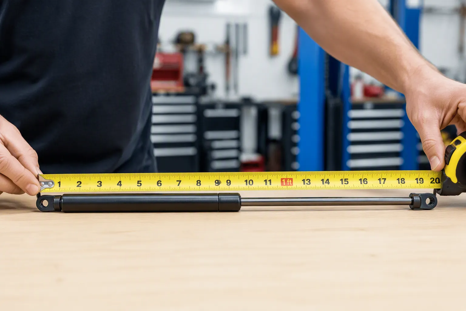
In a manufacturing environment, measuring the extended and compressed lengths requires calibrated digital calipers and dedicated test fixtures. Extend the gas spring fully. Measure from the center of one mounting hole to the center of the other mounting hole. This distance is the extended length. For the compressed length, compress the spring completely using a pneumatic press and measure the same center-to-center distance. The difference between these two numbers equals the stroke length.
The most frequent measurement error in aftermarket replacements is failing to measure from the exact center of the mounting holes. Measuring from fitting edges or cylinder ends leads to errors of 20-30 mm, which causes replacements that bind or fail to compress.
The compressed length measurement carries additional importance. It determines whether the gas spring can fit in the closed position without bottoming out. Follow these rules for accuracy:
Verify the distance between the two mounting points in the closed CAD model.
This distance must be strictly greater than the compressed length of the gas strut plus a safety tolerance.
If the compressed length is verified incorrectly, the strut cannot fully compress when the lid closes. This leads to catastrophic installation failure, bent piston rods, or shattered hinge mounts.
The attachment points and required force are calculated from the overall length and stroke of the struts. If the compressed length is measured incorrectly, the installer purchases struts with the wrong overall length. This shifts both attachment points. The force calculation changes accordingly. The result is an automotive hydraulic strut that either cannot fully compress or provides incorrect lifting force.
Over-compressing a gas spring beyond its designed limits leads to internal seal destruction and immediate failure. The compressed length must be engineered and calculated accurately before tooling begins.
Rod and Tube Diameters Standardization
Rod and tube diameters determine whether the gas spring fits into the existing mounting brackets and dictate the overall force capacity. Use precision calipers to measure the rod diameter and the outer tube diameter. These two dimensions are essential for ordering a direct replacement or designing a new OEM application.
Standard sizes for automotive gas springs follow a specific pairing system. Each rod diameter corresponds to a designated tube diameter to ensure adequate internal gas volume and structural integrity. The table below shows the common series utilized in the industry:
Series | Tube (mm) | Rod (mm) |
|---|---|---|
6/15 | 15 | 6 |
8/18 | 18 | 8 |
10/22 | 22 | 10 |
12/25 | 25 | 12 |
14/28 | 28 | 14 |
The rod diameter affects the force output of the gas spring. A larger rod displaces more internal volume, which influences the pressure curve and damping force. The tube diameter determines the volume of nitrogen gas and oil inside the cylinder. Both dimensions must match the original equipment specifications to ensure proper fitment in the vehicle's mounting brackets.
Measuring these diameters accurately prevents assembly line errors. A 10 mm rod looks visually similar to an 8 mm rod, but the force difference is massive. Always record the measurement in millimeters. Compare it against the manufacturer data.
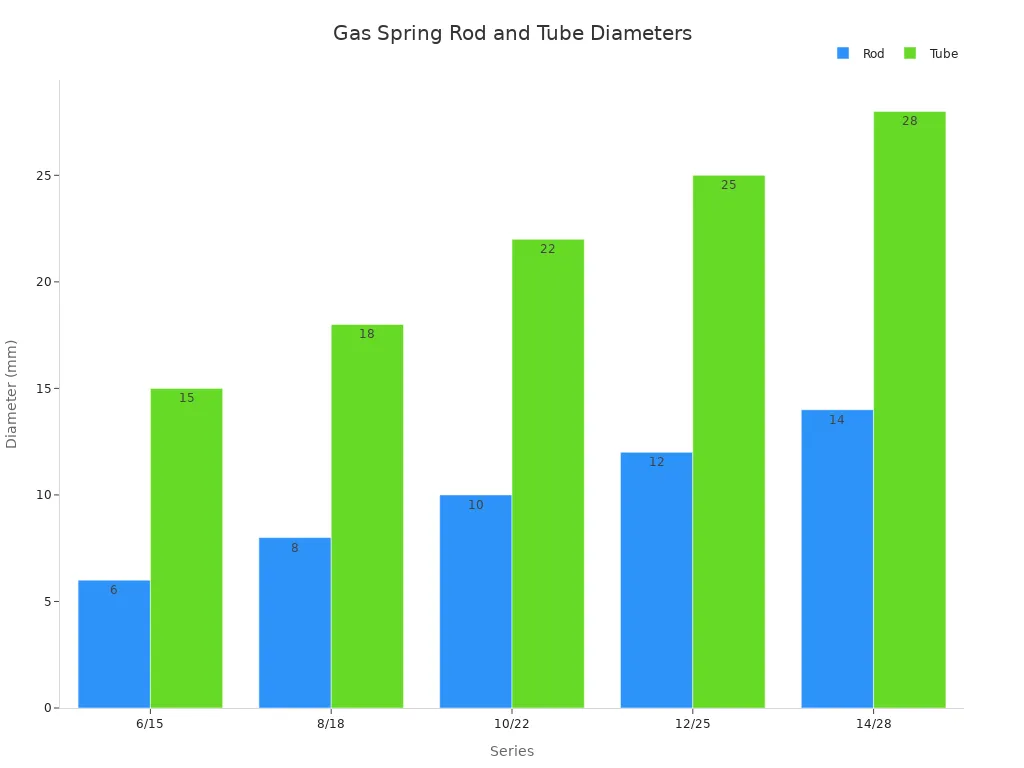
The chart shows the relationship between rod and tube sizes across the standard series. The tube diameter consistently exceeds the rod diameter by 9 to 14 mm. This pattern confirms the standardized pairing system used globally in the automotive industry.
Rod and tube fitment applies to the mounting hardware as well. The end fittings must match the rod diameter. Ball sockets, eyelets, and other connectors require specific rod sizes. Measure the rod diameter before ordering replacement fittings to ensure a complete and functional installation.
Gas Spring Installation and Assembly Protocols
Matching Markings and Lid Angle Dynamics
High-quality OEM gas springs carry laser-printed or engraved markings. These include the force rating in Newtons, the stroke length, and customer-specific part numbers. The force rating indicates lifting capacity, and the stroke length confirms travel distance. Check these numbers against your original engineering BOM (Bill of Materials). Matching them ensures a direct replacement and simplifies assembly line installation.
If markings are absent, calculate the required force using the lid weight and the hinge pivot point. The lid angle at the fully open position affects the calculation. A steeper angle changes the moment arm. The gas spring must deliver adequate force at that specific angle. Double-check your installation measurements before ordering bulk batches.
The mounting orientation affects damping. Rod-down mounting keeps the internal oil near the piston seal. This supports consistent damping and prevents dry friction. Maximum damping occurs when the piston reaches the oil column near full extension. Horizontal or rod-up mounting changes the oil position, leading to inconsistent damping. The tailgate may move faster near the end of travel, causing a loud slamming noise. If NVH and damping are critical, always design for rod-down orientation.
Mounting Hardware and Positioning
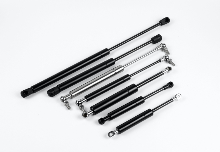
Select the right end fittings for your mounting brackets. Common types include eyelets, ball joints, and clevis ends.
End Fitting Type | Design Feature | Functional Benefit |
|---|---|---|
Eyelets | Looped end for pin connection | Provides a fixed, robust pivot point |
Ball Joints | Spherical joint | Accommodates complex 3D angular movement |
Clevis Ends | U-shaped design | Allows for easy attachment with a pin or bolt |
Choose the fitting that matches your vehicle's brackets. The fitting must allow free pivoting without resistance to prevent side-loading the piston rod.
Positioning is critical for proper installation. Mount the gas spring rod-down. The gas spring must align perfectly with its intended line of motion. Misalignment introduces lateral force on the rod. The rod presses against one side of the guide, causing uneven wear and eventual leakage. Measure the mounting points before securing the spring. Ensure the gas spring can compress fully without binding. Proper alignment prevents premature wear and ensures the tailgate operates smoothly for the vehicle's entire lifespan.
Types of Automotive Gas Springs
Standard, Lockable, and Traction Applications
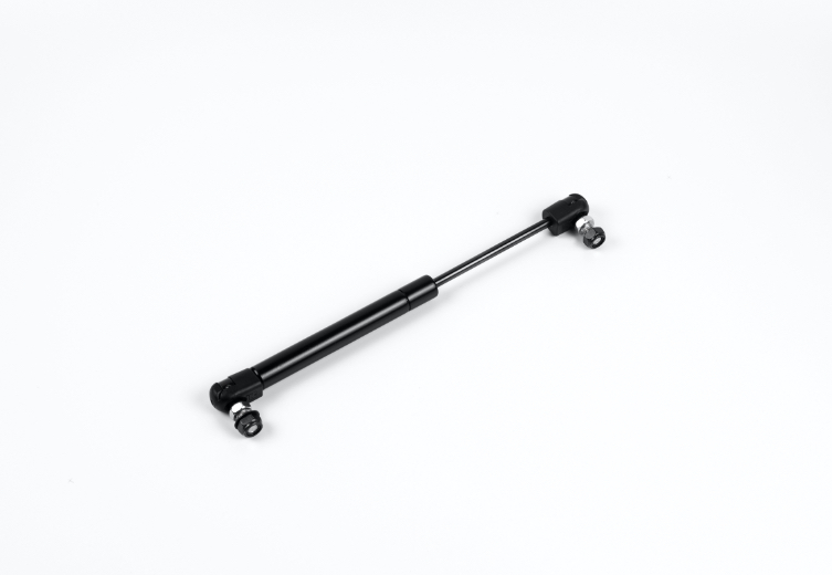
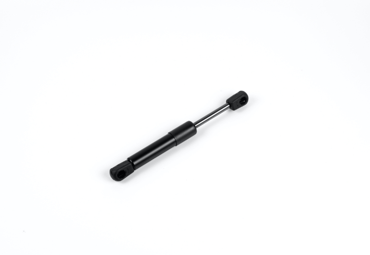
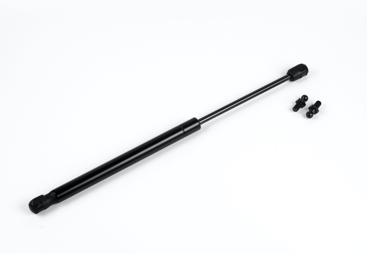
Standard gas springs, also known as compression springs, provide a constant lifting force. They excel in counterbalancing hoods, trunks, and heavy tailgate lift supports. These units contain pressurized nitrogen gas that pushes the piston rod outward. Most automotive applications rely on this type for simple, reliable operation.
Lockable gas springs add a valve mechanism that stops piston movement at any position. This feature holds the lid open at any angle. Common automotive applications include motorhome beds, specialized truck compartments, and adjustable rear spoilers. These springs allow secure positioning without external mechanical latches, improving safety and convenience in commercial vehicles.
Automotive returnable rack systems and mobile medical units also depend heavily on lockable gas springs. The springs hold heavy access panels open during loading and unloading, reducing worker strain and speeding up logistics operations.
Traction gas springs operate in reverse of compression springs. Instead of pushing outward, their natural state is retracted, and they provide a strong pulling force when extended. JUTENG manufactures all these types, offering customized force curves to meet the exact demands of modern vehicle architectures.
Material and Environmental Resistance
Material selection determines the lifespan of an automotive gas spring, especially for under-hood or exterior chassis applications. Standard carbon steel tubes with standard painting work well in dry, temperate environments. However, moisture, mud, and road salt accelerate corrosion. Rust on the piston rod compromises the seal and leads to rapid gas leakage.
To combat this, JUTENG offers advanced surface treatments like QPQ (Quench-Polish-Quench) and Stainless steel (AISI 304/316L) options. Our stainless steel and treated components easily pass 500 hours of continuous salt spray exposure under the strict ASTM-B117 test standard. This simulates harsh coastal or winter road conditions. These springs deliver up to 100,000 life cycles, backed by a comprehensive quality warranty. The extended service life justifies the investment for demanding automotive environments.
Operating temperature drastically affects gas spring performance. Extreme heat increases internal pressure, raising the output force. Extreme cold reduces pressure and force. JUTENG provides customization services for OEM/ODM orders. Our engineers specify specialized multi-lip seals and low-viscosity oils for extreme conditions (-40°C to +80°C), ensuring reliable operation in any global climate.
How Automotive Gas Springs Work
Gas Pressure and Hydraulic Damping
A gas spring operates on a precise thermodynamic principle. Pressurized nitrogen gas fills the cylinder. This gas pushes against the piston rod, creating the lifting force. The rod diameter and gas pressure determine the output force.
The oil inside the cylinder serves a critical damping purpose. It controls the speed of extension, ensuring the trunk doesn't fly open dangerously. The piston contains a flow-restriction orifice. As the rod moves, the oil must pass through this restriction. This creates hydraulic resistance that slows the piston's movement, providing the premium, quiet feel expected in modern vehicles.
The orifice permits gas transfer between chambers.
Oil passing through the same restriction creates hydraulic resistance.
This resistance dampens and slows the extension speed, especially at the end of the stroke.
Temperature affects the internal pressure. For every 10°C change, the force output shifts by approximately 3% to 4%. Force decreases with a temperature drop. The Ideal Gas Law (PV = nRT) governs this behavior. This relationship explains why tailgates sometimes struggle to stay open in freezing winter conditions if the initial force margin was calculated too tightly.
The force output of a gas spring is directly proportional to the gas pressure and the piston area, as expressed by the formula F = P × A, where F is force, P is pressure, and A is the effective area of the piston.
Force and Lift Calculation in OEM Design
Selecting the correct force requires a straightforward calculation during the prototyping phase. The formula uses three values: the lid weight, the distance from the hinge to the center of gravity, and the distance from the hinge to the spring mounting point.
Core Formula: F = (W × D) / L Where:
W = object weight (N)
D = distance from hinge to center of gravity (m)
L = distance from hinge to spring attachment point (m)
Worked Example: For a 10 kg composite hood (W = 98 N), with D = 0.4 m and L = 0.6 m: F = (98 × 0.4) / 0.6 = 65.3 N. This gives the absolute minimum required spring force.
This result represents the theoretical minimum force. Professional engineers always add a safety margin of 10% to 15%. The extra force compensates for seal friction, grease viscosity, and winter temperature drops.
Complex installations involving four-bar hinges or dual-spring setups require advanced CAD simulation. JUTENG's engineering team provides comprehensive design support for these situations, ensuring your custom application is perfectly balanced.
B2B Storage and Handling Protocols
Warehouse Orientation and Climate Control
For B2B warehouses and assembly lines, store gas springs with the rod pointing downward. This position keeps the piston rod seal submerged in the internal oil. The oil layer lubricates the seal and prevents dry friction during long-term storage. Dry friction accelerates seal degradation, allowing nitrogen to escape. A spring that loses pressure on the shelf will cause warranty claims before the vehicle is even sold. Store unused springs in their original packaging in a clean, dry, and temperature-controlled area.
Safety Precautions in Manufacturing
Never attempt to disassemble, machine, or weld a gas spring. The cylinder contains highly pressurized nitrogen gas. Improper handling can cause a sudden, explosive release of compressed gas, leading to severe workplace injuries.
Improper handling or puncturing may damage the gas spring's pressure tube, resulting in the high-speed ejection of internal components, which poses a critical safety hazard to assembly line workers.
Always wear ANSI-approved safety glasses when handling bulk orders. Avoid dropping the springs or damaging the rod surface with heavy tools. Scratches or nicks on the rod will immediately compromise the seal once installed. Only trained personnel should perform end-fitting replacements. Follow JUTENG's manufacturer instructions carefully to ensure a safe working environment.
Follow this simple engineering checklist for selecting the right automotive gas spring:
Extract the exact lid weight and 3D center of gravity from your CAD data.
Verify the stroke length and BIW packaging space constraints.
Choose the material and type based on environmental exposure and functional needs.
Getting these steps right ensures a perfect fit for your production line. To guarantee the highest quality, every batch of OEM car gas springs produced at JUTENG undergoes rigorous validation. We utilize a 10-meter drop tower capable of 40 km/h impact speeds and high-speed camera systems to analyze the damping behavior and structural integrity of our struts under extreme stress. This ensures your vehicle's hoods and trunks operate flawlessly.
Need assistance with a complex vehicle architecture? JUTENG's engineering team offers personalized design support and rapid prototyping. Contact us today to discuss your custom automotive gas spring requirements.
FAQ
How do I know if my gas spring force is too high or too low?
A gas spring with excessive force makes the lid difficult to close and puts stress on the hinges. Insufficient force causes the lid to sag or fall shut, especially in cold weather. Test the spring in a climate chamber across the -40°C to +80°C range to ensure it stays in position without drifting.
Can I replace an OEM gas spring with a different stroke length?
No. The stroke length must match your vehicle's mounting space exactly. A longer stroke prevents full compression and can bend the piston rod when the trunk is closed. A shorter stroke limits the opening angle. Always measure the OEM part or refer to the vehicle's service manual.
What does rod-down mounting mean for my installation?
Rod-down mounting positions the piston rod pointing downward towards the ground. This orientation ensures the internal oil constantly lubricates the main seal, reducing friction and preventing gas permeation. Always design brackets to accommodate rod-down mounting whenever vehicle geometry allows.
How does temperature affect automotive gas spring performance?
Force output shifts approximately 3% to 4% for every 10°C change due to the Ideal Gas Law. Cold weather reduces lifting force, which is why JUTENG engineers always add a 15% safety margin to the baseline calculation to ensure reliable winter operation.
Are stainless steel gas springs worth the extra cost for auto parts?
For exterior applications like tailgate lift supports or marine applications, absolutely. Stainless steel (304/316L) units resist corrosion effectively and pass 500 hours of ASTM-B117 salt spray testing. For under-hood applications, carbon steel with advanced QPQ treatment is usually sufficient and more cost-effective.