




Main Difference Between a Gas Strut and a Gas Damper
The Core Difference (Short Answer)
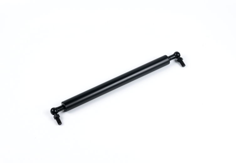
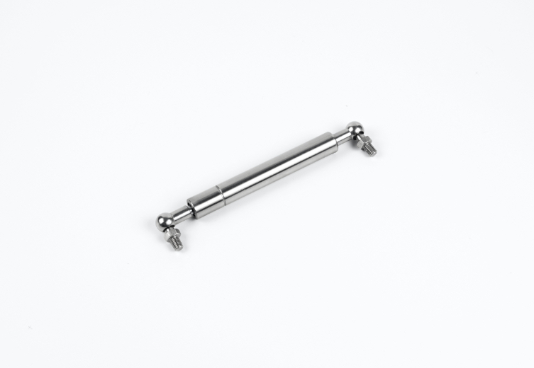
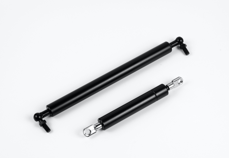
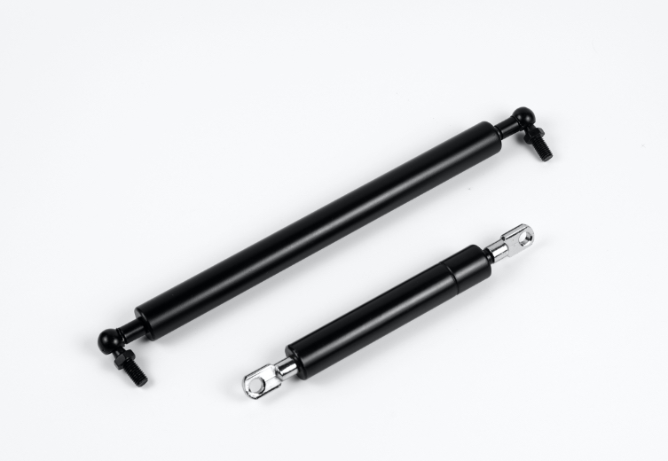
A gas strut (or gas spring) is an active component that uses high-pressure nitrogen to generate a pushing force to act as a lift support or counterbalance for heavy loads. A gas damper is a passive component that uses hydraulic fluid resistance to control speed and absorb shock, acting as a shock absorber. Simply put: Struts support weight; dampers control motion.
A pneumatic strut generates internal pressure to push loads outward continuously, serving as an active power source for lifting heavy access covers. In contrast, a gas damper absorbs kinetic energy to slow down movement without generating pushing force, functioning as a soft-close mechanism. Understanding these key differences helps builders select the exact component for smooth motion control.
Feature | Force Generation | Energy Absorption |
|---|---|---|
Primary Component | gas spring assembly | Hydraulic fluid resistance mechanism |
Working Medium | Highly compressed nitrogen gas | Non-pressurized hydraulic oil |
Default Position | Fully extended outward | Retains last manual position |
This functional contrast defines whether a mechanical system creates active lifting support or provides controlled speed reduction during daily operation.
Key Takeaways
Gas struts push heavy loads outward using high-pressure nitrogen to help lift lids and covers as an active counterbalance.
Gas dampers absorb movement energy using fluid resistance to stop fast slamming and control travel speed.
Engineers choose gas struts for active lifting assistance and gas dampers for controlled speed reduction.
Always install gas struts with the piston rod pointing downward to keep the rubber seals lubricated.
Working Principle of a Gas Strut
How Internal Gas Pressure Generates Force
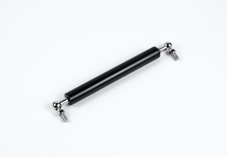
Highly compressed nitrogen gas inside the cylinder acts directly on the piston rod. This pressure pushes the rod outward consistently. The outward force depends on the internal pressure and rod diameter.
Mathematical Formula: The output force (F) generated by a gas strut is calculated by multiplying the internal charge pressure (P) by the cross-sectional area of the piston rod (A), represented as: Force = Pressure × Area (F = P × A).
Relationship: Given a fixed charge pressure, increasing the rod's diameter (and thus its surface area) directly yields a greater output force.
Practical Calculation Example:
Given Parameters: Internal charge pressure of 4 MPa (40 bar) and a rod radius of 0.005 m (from a 10 mm diameter rod).
Area Calculation: A = π × r² = 3.14 × (0.005 m)²
Force Calculation: F = 4 MPa × (3.14 × 0.005² m²) = 315 N
Key Components and Mechanical Design
A gas spring relies on specialized internal parts to maintain high pressure over extended service cycles.
Guide and Seal Assembly: Employs durable rubber or advanced elastomeric seals combined with precision guides made from brass, zinc, or high-performance plastic composites to prevent gas escape.
Bearing Sleeves: Ensure fluid articulation while minimizing friction and surface wear on the rod.
Precision Tube Surface Finish: A smooth internal wall finish directly mitigates seal degradation, extending overall cycle life and preserving seal performance under pressure.
Common Applications for Counterbalanced Lifting
A compressed gas spring provides reliable load assistance across many mechanical setups. Specialized variations offer versatile support choices for distinct operational needs. For example, lockable gas springs hold adjustable seating positions securely, while traction gas springs pull components together inside tight installation spaces.
Sector | Primary Applications |
|---|---|
Automotive | • Engine hoods |
Industrial & Manufacturing | • Assembly line machinery |
Heavy Machinery & Agriculture | • Construction cab-tilt mechanisms |
A standard gas strut remains the ideal choice whenever equipment requires smooth lifting assistance and easy handle control.
Function and Mechanism of a Gas Damper
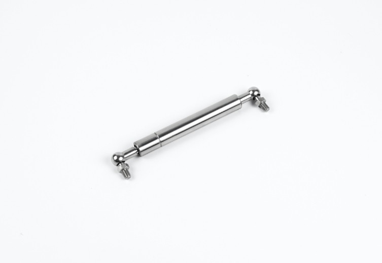
Unlike force-generating struts, a gas damper controls speed and absorbs unwanted movement in mechanical assemblies. It acts as an energy-absorbing element rather than a lifting helper.
How Fluid Resistance Absorbs Kinetic Energy
Inside a gas damper, internal oil or gas absorbs moving energy. The displacement of the rod forces internal fluid through small openings to control speed smoothly. This kinetic energy conversion process follows three distinct physical stages:
Mechanical Motion: Piston displacement forces hydraulic fluid through restricted metering orifices or narrow passages.
Flow Resistance & Viscous Friction: The restricted passage creates substantial flow resistance and high pressure drop, inducing viscous friction within the fluid.
Thermal Energy Conversion: This frictional interaction and fluid shearing convert the mechanical kinetic energy directly into dissipated heat (thermal energy).
Key Takeaway: Dampers do not push heavy loads upward. They convert kinetic energy into heat to stop sharp impacts.
Gas Damper vs. Hydraulic Damper: Is There a Difference?
In industrial terminology, "gas damper" and "hydraulic damper" (or oil damper) often refer to the exact same component. While the name implies the use of gas, standard dampers rely primarily on hydraulic oil to create viscous drag. The low-pressure gas (usually nitrogen) inside the cylinder only serves to prevent the oil from cavitating (forming bubbles) during rapid movement, ensuring smooth shock absorption. Therefore, when engineers search for a soft-close mechanism or shock absorber, both terms lead to the same fluid-based motion control hardware.
Compression Damping vs Extension Damping
Manufacturers adjust internal valve designs to control movement in specific directions. Mechanical systems require distinct damping behaviors depending on force direction.
A compression damper provides motion resistance when an external force pushes the piston rod into the cylinder tube. This setup prevents heavy lids from closing too quickly.
An extension damper offers speed control while the piston rod pulls outward from the cylinder. Operators use this mechanism to prevent sudden spring releases or fast opening speeds.
Certain dual-acting designs combine both mechanisms. These specialized units deliver controlled resistance during inward and outward stroke movements simultaneously.
Primary Use Cases for Controlled Deceleration
Dampers protect mechanical hardware, eliminate noisy impacts, and increase user safety during operation. They regulate speed in applications where uncontrolled movement creates hazards.
Industry Sector | Typical Applications | Operational Benefit |
|---|---|---|
Commercial Furniture | Soft-close cabinets and medical carts | Prevents slamming and reduces mechanical noise |
Industrial Safety | Heavy machine guards and safety gates | Absorbs impact force during emergency stops |
Automotive | Glove boxes and tailgate drop controls | Ensures smooth drop motion without bouncing |
Choosing a precise motion control unit guarantees long component life and smooth equipment handling.
Comparing Motion Control Performance
Active Force vs Motion Resistance
Mechanical systems require distinct motion behaviors depending on structural demands. The fundamental contrast between components lies in energy storage versus energy dissipation. An active power element stores energy inside a pressure chamber. A passive resistance element absorbs kinetic energy during mechanical movement.
A gas spring uses stored potential energy to perform physical work. High-pressure nitrogen gas charges the internal cylinder volume. This pressurized gas forces the piston rod outward automatically. The mechanical assembly outputs continuous lifting assistance throughout the entire stroke length. Mechanical engineers select this component to offset component weight, lift heavy machinery hatches, or assist human operators during manual lifting operations.
Conversely, a unit built for motion resistance generates zero static extension force. The system contains non-pressurized fluid or low-pressure gas. Moving parts encounter resistance only when external forces push or pull the actuator rod. The device converts moving kinetic energy into thermal energy through fluid shearing.
Performance Insight: Active force devices push loads outward automatically. Resistance devices require external kinetic energy to activate their slowing action.
The force-velocity profile shows distinct mechanical behavior:
Performance Metric | Active Force System | Motion Resistance System |
|---|---|---|
Primary Output | Constant dynamic thrust | Speed-proportional resistance |
Static State Behavior | Extends rod to maximum stroke | Holds current position without moving |
Energy Cycle | Stores potential energy | Dissipates kinetic energy into heat |
Speed Dependence | Force remains relatively constant | Resistance increases with higher velocity |
Continuous Damping vs End-of-Stroke Cushioning
Motion control hardware manages physical velocity in two distinct operational styles. Engineers select specific fluid control methods based on safety requirements and mechanical travel paths.
Continuous damping regulates velocity evenly across the entire movement path. Internal hydraulic fluid passes through fixed metering orifices on the piston head. The internal fluid flows at a controlled rate from one chamber to another. This action maintains steady speed control from start to finish. Heavy industrial doors utilize continuous resistance to prevent runaway movement during opening cycles.
End-of-stroke cushioning focuses deceleration forces at the travel limits. The internal piston moves freely through the central portion of the stroke. Resistance remains minimal during initial movement. The piston approaches the end cap and enters a reduced fluid bypass zone. This hydraulic deceleration pocket slows movement right before full extension or compression.
[Start of Stroke] ----> Free Movement Zone ----> [Cushioning Zone] ----> [Soft Stop] (Minimal Resistance) (Restricted Fluid)
System designers configure these travel profiles using internal bypass grooves. Machine operators achieve exact speed profiles by matching internal hydraulic paths to operational speeds.
Structural Differences in Internal Seals and Valves
Internal mechanical structures differ significantly between lifting units and motion control units. Gas strut components contain high-pressure gas charges up to 200 bar. Internal dynamic seals must prevent gas molecules from escaping past the sliding piston rod. Manufacturers use specialized lip seals combined with hardened steel guide bushings. Lubrication oil sits at the bottom of the cylinder tube to keep primary dynamic seals moist during static resting periods.
Internal fluid resistance components rely on complex valve disc stacks and dynamic piston seals. Dampers and gas springs maintain structural differences inside their main body tubes:
Piston Head Construction: Dampers feature multi-stage shim stacks, flexible valve plates, and variable orifices. These dynamic valves open or close based on fluid flow direction and fluid velocity. Lifting units use simple piston seals with broad bypass channels.
Internal Medium Ratio: Pushing mechanisms hold mostly compressed nitrogen gas with a small quantity of lubricating oil. Energy absorbers contain high volumes of hydraulic oil to provide dense viscous resistance.
Seal Package Design: High-pressure gas seals prevent pneumatic leakage past moving rods. Fluid control seals prevent high-pressure hydraulic oil leakage during violent impact spikes.
These internal mechanical structural features highlight key differences in mechanical design. Selecting correct internal valve configurations ensures long operational life, smooth velocity reduction, and stable equipment performance across heavy industrial environments.
Selection Guide for Mechanical Applications
Selecting the ideal mechanism requires a clear evaluation of mechanical goals. Engineers must determine whether a system needs active force support, controlled speed regulation, or a balance of both functions. Following specific rules helps designers choose the right component for long-term operational success.
Selecting a Gas Strut for Load Support
An engineer selects a gas strut when an application demands active force generation to assist with manual lifting. Heavy access covers, industrial machinery guards, and automotive hoods require continuous outward pressure to counteract gravity. The internal nitrogen gas charge acts as an invisible helper, reducing human exertion and keeping heavy lids open safely.
Calculating the necessary extension force prevents operational failures and equipment wear. Engineers analyze the rotational torque around the hinge pivot to balance gravitational forces. The exact push force calculation uses dynamic torque variables across the physical travel path.
Variable | Parameter Name | Measurement Unit | Description |
|---|---|---|---|
F | Required Dynamic Force | Newtons (N) | The required individual push force calculated for each strut. |
G | Lid Weight | Newtons (N) | Total gravitational force of the cover (convert kg to N by multiplying mass by 9.81). |
L | Center of Gravity Distance | Millimeters (mm) | Horizontal measurement starting from the hinge pivot point to the lid's center of gravity. |
N | Number of Springs | Count | Total quantity of gas struts utilized (typically 2 mounted symmetrically). |
b | Effective Lever Arm | Millimeters (mm) | Shortest distance from the hinge axis to the gas strut centerline when closed. |
Designers calculate exact force needs through a systematic mechanical process:
Torque Balance Principle: Analyze the rotational force around the hinge pivot to balance the gravitational torque from the cover's weight with the lifting torque of the struts.
Identify Center of Gravity: Locate the horizontal distance (L). For uniform doors, it resides at the geometric midpoint; for irregular doors, determine it via 3D CAD modeling or moments.
Apply the Core Equation: Compute theoretical push force using the mechanical advantage formula: F = (G × L) / (2 × N × b).
Factor in Safety: Append a safety margin to the calculated result to account for practical friction and performance variations.
Selecting compressed gas springs guarantees reliable opening assistance. For specialized applications requiring position retention, lockable gas springs provide immediate stop capabilities along the stroke. The gas spring system provides smooth movement while handling high structural loads.
Design Tip: Always mount the gas spring with the piston rod pointing downward in the rested state. This positioning maintains dynamic rod seal lubrication and ensures effective end-of-stroke hydraulic cushioning. For safe handling during mounting, refer to our Step-by-Step Guide to Compressing a Gas Spring Safely.
Selecting a Gas Damper for Motion Resistance
A gas damper becomes necessary when an application requires speed regulation without additional lifting assistance. Uncontrolled acceleration can cause dangerous slamming, structural fatigue, or severe pinch hazards. Energy-absorbing components maintain smooth mechanical movement across automotive tailgates, industrial safety gates, and commercial furniture panels.
To select a motion resistance unit, evaluate these key operational parameters:
Stroke Speed: Determine the maximum allowable velocity for component travel.
Impact Mass: Calculate the moving weight to establish correct kinetic energy absorption.
Damping Direction: Choose between single-acting resistance during compression or extension, or dual-acting resistance in both directions.
Unlike active lifting units, a motion control unit contains restricted fluid channels to create viscous drag. The system absorbs kinetic impact energy and dissipates thermal energy efficiently.
Combining Struts and Dampers in Dual Systems
Complex mechanical setups often require simultaneous force assistance and motion resistance. Heavy lids may need strong outward thrust during opening, yet demand controlled velocity during closing. Engineers can deploy separate dampers and gas springs side-by-side within a single mechanical framework.
Engineering Innovation: Modern manufacturers like czjuteng design hybrid motion solutions. These engineered assemblies combine strong opening force and controlled closing speed inside a single compact cylinder.
Integrated solutions eliminate the extra cost and space required for dual hardware setups. Furthermore, manufacturers like czjuteng provide expert custom design services. Engineering teams can customize non-standard stroke lengths, specialized mounting fittings, and unique force specifications tailored directly to your operational machinery requirements. Using specialized hardware ensures smooth operation, operator safety, and component durability across demanding environments.
Selecting the right motion control hardware comes down to one clear decision rule. Choose a gas spring to push heavy loads and assist manual lifting. Choose a gas damper to absorb kinetic energy and regulate travel speed.
Before purchasing components, verify your system parameters carefully. Designers must evaluate exact force ratings, stroke length, and physical mounting orientation. Always install hardware with the piston rod pointing downward in the fully closed position. Positioning the unit in this manner keeps the seal package continuously lubricated, which promotes smooth movement and prevents premature wear. Matching these critical application variables guarantees high operational safety, consistent performance, and maximum equipment service life.
Partner with JuTeng for Custom Motion Control Solutions
Whether your project requires a high-force pneumatic strut for heavy machinery or a precision viscous drag damper for commercial furniture, selecting the right component is critical. As a trusted manufacturer with over 17 years of industry experience, Changzhou JuTeng Gas Spring provides comprehensive motion control solutions tailored to your exact specifications.
Custom Engineering: Non-standard stroke lengths, specialized mounting fittings, and custom force ratings (10N to 5000N).
Quality Assurance: Manufactured under strict IATF 16949 and ISO quality management systems.
Technical Support: Free 3D CAD modeling assistance and force calculation verification from our engineering team.
Contact Our Engineers for a Free Quote
FAQ
Can a gas strut replace a gas damper in an application?
No, you cannot swap these components directly. A strut pushes outward actively to lift heavy loads. A damper absorbs kinetic energy to slow down movement. Replacing one with the other disrupts total motion control.
Do gas dampers require high internal gas pressure?
Quick Answer: Most dampers rely primarily on hydraulic oil rather than compressed gas.
Standard dampers use non-pressurized fluid to create viscous drag. Some models include low-pressure gas chambers to stabilize oil flow, but they do not produce pushing force.
Why should you install a gas strut with the rod pointing downward?
Seal Lubrication: Keeps dynamic rubber seals moist to prevent pressure leaks.
Friction Reduction: Reduces operational wear during daily movement cycles.
End Cushioning: Guarantees effective hydraulic dampening near full extension.
How do lockable gas springs differ from standard struts?
Lockable gas springs contain internal valve mechanisms that stop the rod at any position along the stroke. Standard models extend continuously until reaching maximum length without intermediate stopping points.