



HOW TO DESIGN GAS SPRING
here’s a practical, engineer-friendly walkthrough for designing a single-acting gas spring (strut). I’ll give the key steps, the necessary formulas (with a worked numeric example), material/parts guidance, and a short testing/checklist you can follow.
1) Start with requirements (what you should decide first)
Required force (N) at the operating angle(s) and stroke position(s).
Stroke (mm) — travel length required.
Mounting geometry (eye/ball/spherical ends, pivots, angles).
Operating temperature range (°C).
Required lifetime (cycles) and duty (how often it moves).
Environmental needs (corrosion resistance, cleanliness).
2) Core physics / formulas
Cylinder bore area (piston area):
(m²), where is bore diameter in meters.Gas force (idealized):
(N), where is internal gas pressure in Pa.Include friction and safety margin:
Note: when the rod is retracted the rod-side effective area is smaller by the rod cross-section: . So the force when compressed/rod-side is lower — account for this if your application needs holding force in both positions.
3) Worked example (showing arithmetic step-by-step)
Goal: hold 250 N of load. Assume internal friction ≈ 10 N. Choose an initial bore of 20 mm to see required pressure.
Convert bore to meters: .
Area .
(m²).
(m²).
(approx).
Net force needed = .
Pressure .
Convert to bar: .
So with a 20 mm bore you’d need roughly 8.3 bar of nitrogen to produce ~250 N of extension force (including friction).
If you pick a larger bore, pressure required drops; pick smaller bore and pressure rises. Always stay within standard gas spring maximum pressures and safety margins.
4) Practical design choices & notes
Gas: nitrogen (inert), precharged during assembly.
Seals: polyurethane or NBR for general use; pick low-friction/high-temp seals for extremes.
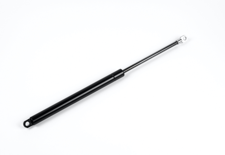
Rod/stem: typically hardened steel (chrome plated) or stainless (SS304/316) for corrosion resistance. Rod diameter affects compressed-side force and buckling.
Cylinder material: steel tube (zinc plated / painted) or stainless for wet/corrosive environments.
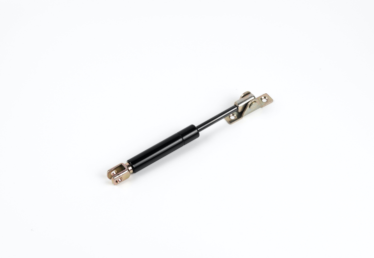
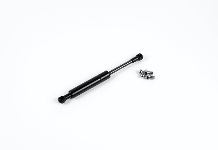
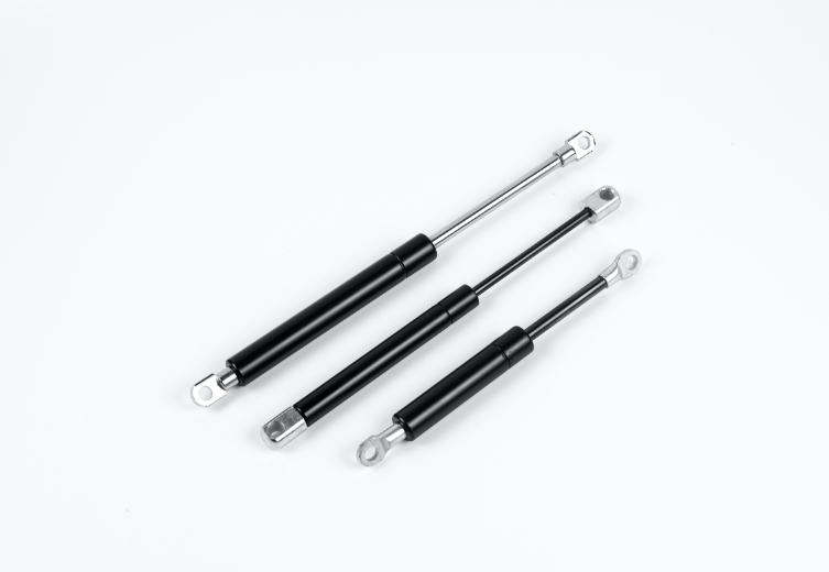
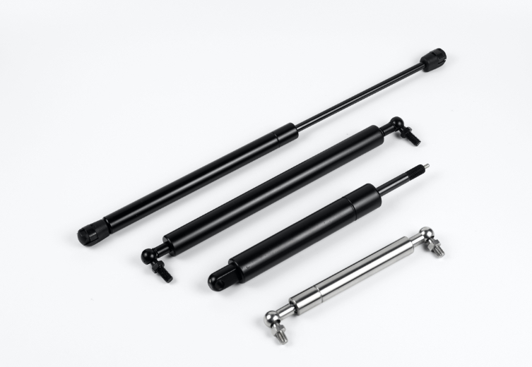
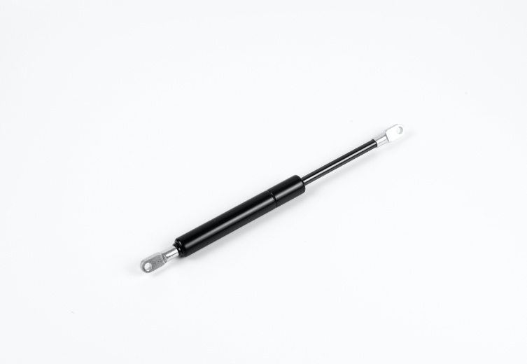
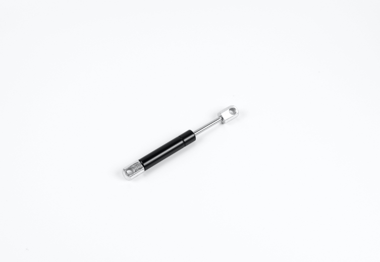
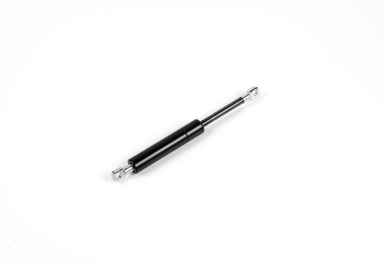
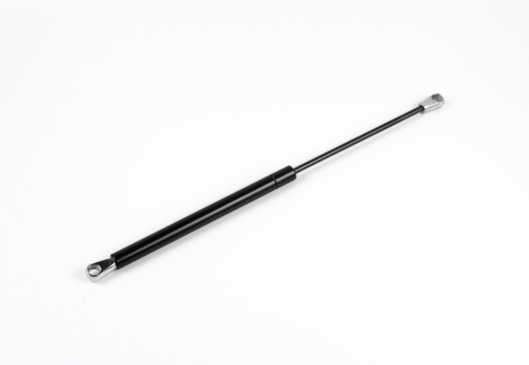
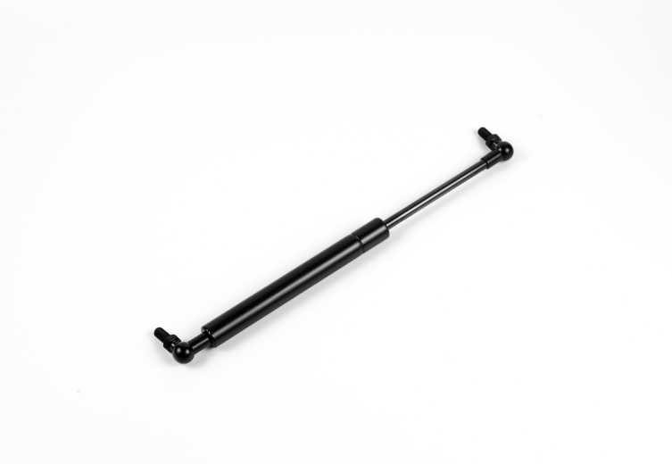
Fittings: ball sockets, eyelets, threaded ends — ensure chosen style matches mounting loads and misalignment.
Damping: internal orifice or external damper if you need controlled velocity; adjustable damping or integrated valves for soft start/stop.
Locking: lockable gas springs use internal mechanics — choose if you need to hold positions mechanically.
Temperature compensation: gas pressure changes with temperature (roughly proportional to absolute temperature). If operating range is wide, increase nominal pressure or select a design tolerant to pressure shift.
Safety & burst: design with safety factors; many manufacturers limit working pressure to well below burst pressure. Include end-of-stroke bumpers or oil cushion if high speeds.
5) Manufacturing & tolerances
Surface finish on rod ≤ Ra 0.2–0.4 µm improves seal life.
Tight concentricity for piston/rod to avoid seal wear.
Control gas fill pressure ±0.1–0.5 bar depending on spec.
Use anti-rotation or anti-buckling features for long slender rods.
6) Testing you should run
Static force check at multiple rod positions (extended/retracted).
Cycle life test: run the intended stroke at expected load for the target cycles (e.g., 50k, 100k).
Leak test (pressure decay).
Temperature test if operating in extremes.
Burst / proof test — per your internal safety rules (do not rely only on burst testing without protective measures).
7) Common pitfalls
Undersizing bore → requires very high pressure (unsafe or nonstandard).
Ignoring rod-side reduced force when retracted.
Failing to account for mounting angle (effective gravity component changes required force).
Poor alignment → seal and rod wear, premature failure.
Not including friction and manufacturing tolerances in calculations.
8) Quick selection workflow (practical)
Pick required force at the operating angle(s).
Choose an initial bore (based on standard sizes: 10, 12, 16, 20, 22, 25, 30 mm etc.).
Compute required pressure (formula above).
Check that the pressure is within typical gas spring manufacture range (and available commercial parts).
Verify compressed-side force (account for rod area).
Choose rod diameter, mounting ends, materials, and seal types.
Prototype and test.
9) Want a tailored example?
Tell me your required force (N), stroke (mm), mounting style (angles or orientation), operating temperature range, and whether you need stainless or standard steel — and I’ll run numbers, pick bore/rod suggestions, show forces extended vs compressed, and propose a candidate part size (or a simple CAD dimension list).